|
Product Details:
Payment & Shipping Terms:
|
| Series: | TE SUPERSEAL 1.0 | Pin: | 34 Pin |
|---|---|---|---|
| Female Part No.: | 4-1437290-0 | Male Part No.: | 2-6447232-3 |
| Material: | PA66+GF Housing, Tinned/gold-plated Copper Terminals | Temperature Range: | -40℃~+125℃ |
| Waterproof Rating: | IP67 | ||
| Highlight: | 6447232-3 Superseal Automotive ECU Connector,4-1437290-0 Superseal Automotive ECU Connector,34 Pin Superseal Automotive ECU Connector |
||
Description
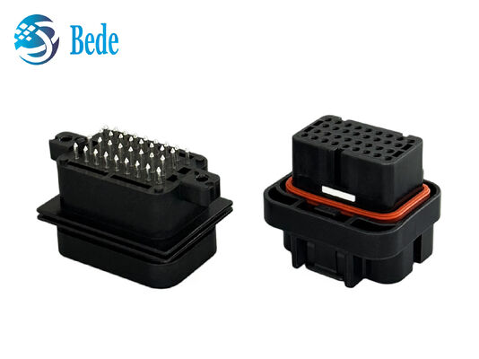
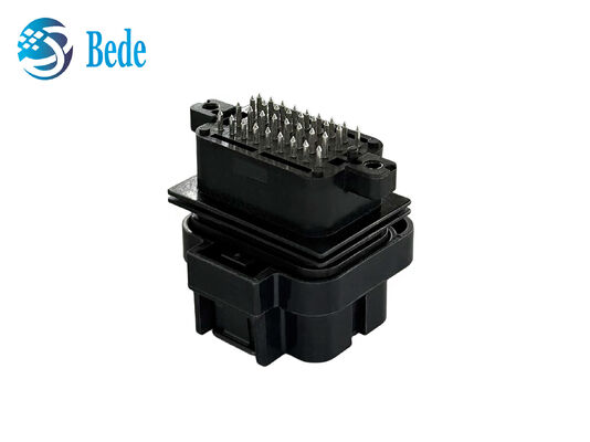
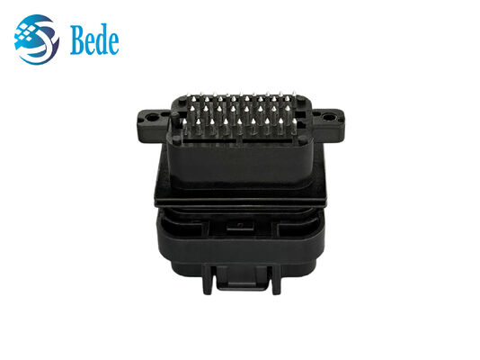
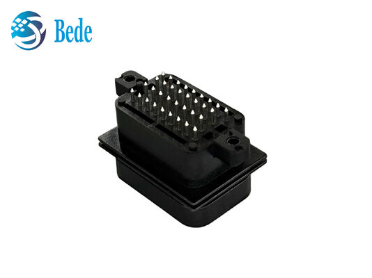
This 34-pin automotive ECU connector is designed for stable electrical connections in vehicle electronic control systems. Based on the SUPERSEAL 1.0 connector format, it features a compact 34-position layout and a sealed structure for automotive applications where protection and connection stability are important. The connector housing is made from automotive-grade engineering plastic, while the sealing system helps protect the connection area from water, dust, and other external contaminants. Its waterproof design helps maintain stable performance in common automotive conditions such as vibration, moisture, and temperature changes. The connector set includes mating components for wire-side and PCB-side applications, providing secure mechanical engagement and reliable electrical connection. Designed as a compatible alternative to TE 4-1437290-0 and 2-6447232-3, this connector is suitable for automotive wiring harnesses, ECU modules, sensors, lighting systems, and other electronic control equipment.
Specifications
| Product Type | Automotive ECU Connector | Connector Series | SUPERSEAL 1.0 Compatible |
| Connector Configuration | Plug & PCB Header | Pitch | 3.0 mm |
| Positions | 34 | Rows | 4 |
| Contact Type | Socket / Pin | Mounting | Wire-to-Board / Wire-to-Device |
| Sealable | Yes |
Product Features
Made from automotive-grade engineering plastic with a sealed housing structure, providing a practical solution for vehicle electronic systems.
The sealing structure helps reduce the entry of water, dust, and other contaminants, making the connector suitable for wet and exposed automotive environments.
The 34-position, 4-row configuration provides multiple connection points in a compact connector body, helping meet the wiring requirements of ECU and other electronic control systems.
The keyed structure and integrated locking feature help guide correct mating and keep the connector securely engaged during vehicle operation.
Designed as a compatible alternative to TE 4-1437290-0 and 2-6447232-3, offering a practical option for replacing or developing compatible automotive connector assemblies.
The wire-side connector supports standard crimping processes, while the PCB-side header is designed for through-hole soldering, supporting efficient wiring harness and PCB assembly.
![]()
Applications
Automotive Wiring Harnesses
Suitable for wiring harness assemblies that require a secure, sealed connection between vehicle cables and electronic modules.
Vehicle Sensors
Can be used to connect sensors with ECU and control modules, supporting stable signal transmission in automotive electronic systems.
Body Control Systems
Suitable for body electronics such as lighting, door control, power management, and other vehicle control functions that require multi-position connections.
Automotive Lighting Systems
Designed for connection points in vehicle lighting assemblies, including control modules and wiring harness interfaces.
Industrial & Off-Road Vehicles
The sealed design can also be considered for electronic control equipment used in trucks, agricultural machinery, construction vehicles, and other mobile equipment.
Step1—Check the Components
Before assembly, check the connector housing, PCB header, terminals, wires, seals, and sealing plugs. Make sure all parts are clean, dry, and free from visible damage.
Step2—Prepare the Wires
Select the appropriate terminal and wire according to the application requirements. Strip the wire carefully without damaging the conductor or insulation. Use a suitable crimping tool to attach the terminal securely to the wire.
Step3—Insert the Terminals
Insert each crimped terminal into the correct cavity from the rear of the connector housing. Push the terminal into position until the locking feature engages. Gently pull the wire to check that the terminal is properly retained.
Step4—Check the Sealing Components
Make sure the wire seals are correctly positioned and seated. For unused cavities, install suitable sealing plugs to help maintain the sealed structure and reduce the entry of water and contaminants.
Step5—Install the PCB Header
Position the PCB header vertically according to the PCB layout. The reference connector uses a through-hole solder termination method. After soldering, inspect the joints to confirm proper electrical connection and mechanical stability.
Step6—Mate the Connectors
Align the keyed features of the wire-side connector and PCB header before mating. Push the two parts together evenly until the locking mechanism is fully engaged. Do not force the connector if the parts are not correctly aligned.
Step7—Perform a Final Check
Inspect the completed assembly for correct terminal position, secure locking, proper wire retention, and visible damage. Confirm that the connector is fully seated before installation in the vehicle or electronic module.
Assembly Notes
Use terminals, seals, sealing plugs, and crimping tools that match the connector design and wire specifications. For mass production, crimping conditions, soldering parameters, and assembly procedures should be verified according to the actual materials, equipment, and manufacturing process used.
FAQ
Are 4-1437290-0 and 2-6447232-3 a matching connector pair?
A:Yes. They represent the wire-side and PCB-side mating components of the connector system.
Can you provide samples before mass production?
A:Yes. Samples can be provided for dimensional inspection, mating tests, assembly evaluation, and application verification before placing a larger production order.
What is the typical lead time for this connector?
A:The lead time depends on the order quantity, product configuration, and production requirements. For standard orders, we will confirm the estimated delivery schedule after reviewing the specific order details.
Can the connector be customized?
A:We can discuss customization options based on your application requirements, including connector configuration, housing design, terminal arrangement, wire assembly, and packaging.
How can I confirm whether this connector is suitable for my application?
A:Please provide the required pin count, mating connector or reference part number, wire size, mounting method, environmental conditions, and application details. Our team can then help check the connector configuration and compatibility.